Producing fiNe-scale wheels
This page shows a quick way to produce fiNe-scale wheels from Fleischmann half-products.
The way that is shown here is not the only one but I think it is one of the fastest and has a low risk on loss of wheels. The principle is to remove the original flange of the wheel and replace it with a new flange and then cut-off everything at the back that is superfluous. One alternative is to turn the whole tyre until a flat face exists and then put on a 1.3 mm width tyre. In this way you can change (reduce) the diameter of the wheel a little. The drawback of that method is that you need a higher reproducable accuracy as all the driving wheels need to have equal diameter. In the method shown here the original relation between axle and tyre keeps intact. If your wheel is uncircular it will not be better afterwards. The flange thickness is less critical as long as it is in the order of 0.3 mm thickness. Any height difference will not influence the running properties. And for wobble there is a rather large tolerance of .1 mm in pointwork.
For turning I use a Unimat lathe, the good old type 3 which is now over 22 years age but still OK.
The first step in the process is to turn a set of rings, which will form the new flanges.
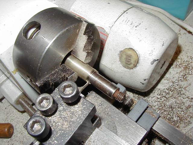
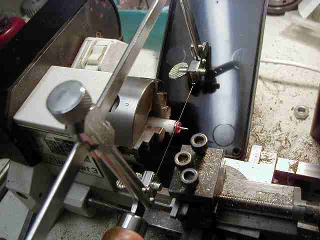
This photo shows the machine, note that I use a higher quality 3-claw than originally supplied.
The wheels used for this session are 8.45 mm diameter with 16 spokes. The usual type for replacements on Prussian loco's. In this case the flanges are turned from 10 mm Nickel-Silver rod but you can use brass too. If you prefer to use brass it is possible to correct the look by electroplating a layer of Nickel on top afterwards.
The outside is turned to a diameter of about 9.6 mm, not critical. The rod is then bored with a 8 mm hole. Use a 8.0 milling cutter as last stage. The photo shows the cutting of a flange using a 0.5 mm cutting steel at a width of of the new flange of approximately 0.4 mm. This cutter is made from 3 mm square Cobalt steel. The 0.5 mm width gives less loss of otherwise useful material, but a wider cutter can be used as well of course. In order to minimise the burrs on the inside of the new flange I put in a close fitting piece of waste steel just before the final cut through. This also takes care that you don't have to search for your flange in the junk below. What you can not see on this photo is that the flange has a (~ 15 degrees) angle on the outside. This is simply a quick haul with a file done when starting out.
Always produce at least the amount of flanges you need plus some surplus for dropping on the workshop floor.
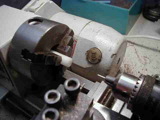
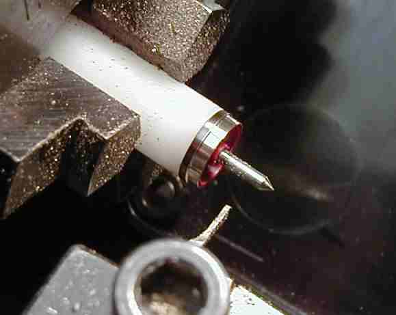
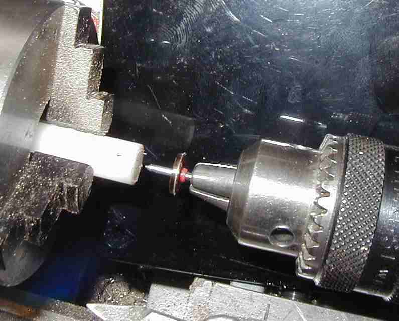
This is the next stage. What you see is a piece of white Delrin in the 3-claw. This has a recess for the extending coupling rod pinhole. The wheel is carried at the outer edge. The inner is drilled with a hole of 1.45 mm. The trick is that the piece of Delrin easily takes the 1.5 mm axle and clamps it with enough force for turning while you can still take the axle out and put it back again over and over. The drill head shows a 1.5 mm axle (from a 2 mm SA wheelset)
This photo shows how to mount a wheel. The axle is pressed in using the tailstock. The wheel rests on the flat face so the axle goes in perpendicular, minimising the chance on wheel wobble. When the axle is pressed home the drill head is loosened. The wheel is not in anyway fixed other than by its own grip. You could pin it by using a pin through the coupling rod pinhole. In practice this is not necessary as you have to treat it gentle anyway. If not, you will not be left without wheel, it simply will fall apart during the process or develop a tremendous wobble due to excessive forces on the plastic part.
Not entirely sharp, but you get the idea.
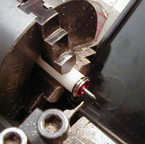
This is the next step, turn off material until you arrive at diameter just larger than your flanges. The dark face is 1mm width and will form the new tyre. The distance to turn off can be measured from the back of the wheel using the indicator wheel on the lathe and the known overwidth dimension.
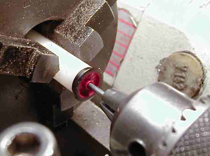
Now we can press on one of our new flanges. This is facilitated if you taper the outer edge of the wheel a bit. This can be done with a file, we will cut it off anyway later. We now have to stick the new flange to the wheel. This can be done with cyanoacrylate glue or with solder. I prefer low melt solder of 70 degrees (for white metal). For this I take the whole lot out of the 3 claw and put it back later in the same position. But if you don't trust this because your 3 claw has its own merites than you better use the glue method.
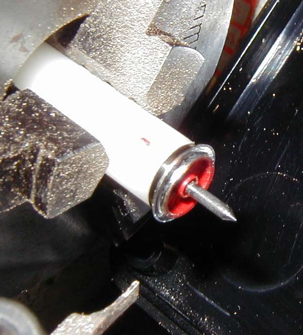
Here we see it after soldering, you also see the mark to replace the rod in the same position.
We can now form the back of the wheel.
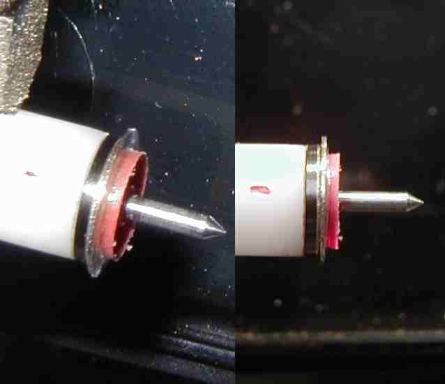
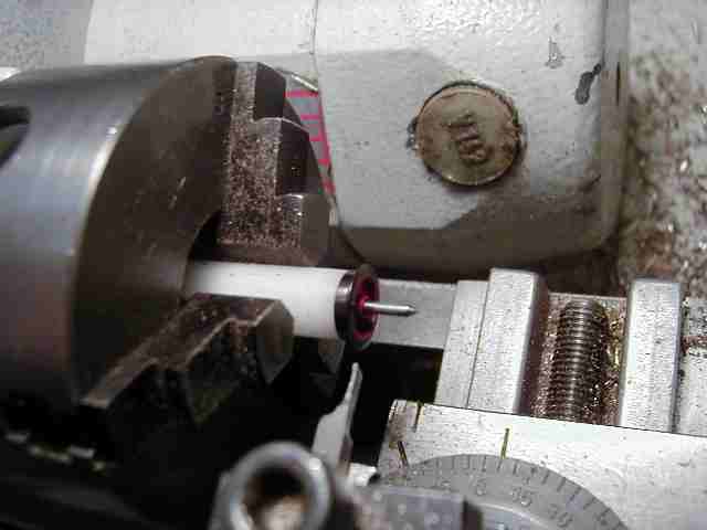
Two views of the wheel. We first cut of the old metal of the rim. We can also see how much taper the plastic part has. Meaning that it will easily fall apart as there is nothing to hold it inside any longer other than a tiny rim at the front.
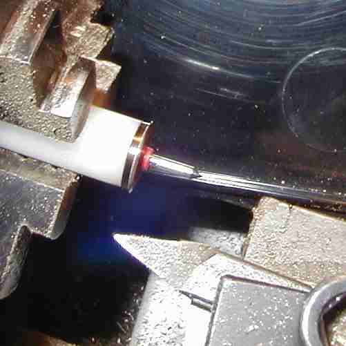
This is how to cut off the plastic without any stress on the wheel. Note put in the sawblade with the teeth wrong way pointing against the rotation of your lathe. This is a 40 teeth/cm sawblade, the finest you can buy. A scalpel can be used too depending on the plastic type of used for the wheel.
Here we see the new flange brought to width with a fine rounded tool. Finishing can be with a fine swiss file #4 and some polishing with glasfiber brush.
Be sure to take out your wheel using the headstock like this. Take it from the drillhead and now gently push the wheel from the axle.
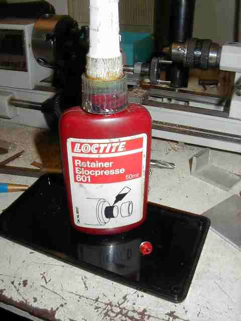
Now for total security use this type of glue to keep the plastic and the metal together. This is very very thin and hardens if no air is available, thus on the interface between plastic and metal. This is age old stuff, nowadays probably has a new package.
author: Henk Oversloot, 5/2/2002